
Threaded Inserts for 3D Printed Parts
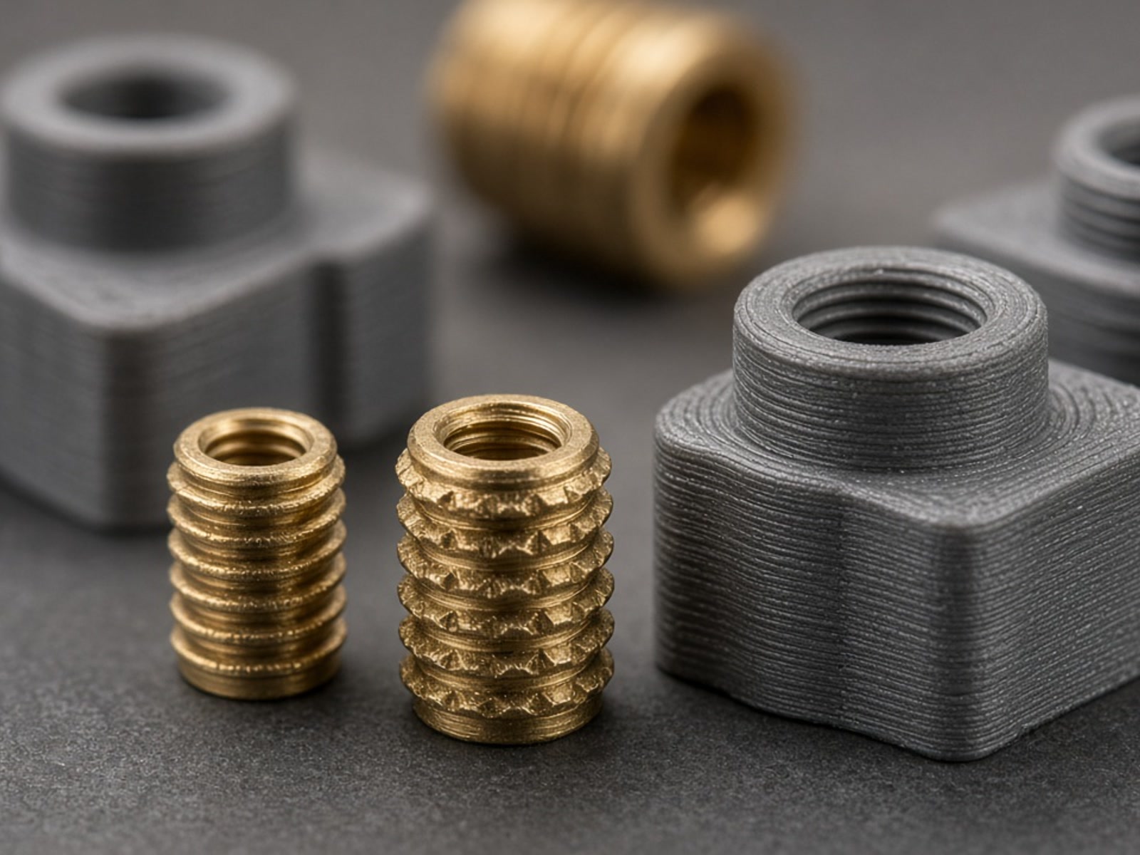
For industrial 3D printed components, achieving reliable, high-strength mechanical connections often requires the integration of threaded inserts. While 3D printing allows for complex geometries and internal channels, standard printed threads can be prone to wear, cross-threading, or failure under high torque.
At RapidPrintParts, we utilize threaded inserts to transform functional prototypes, jigs, and low-volume production parts into robust mechanical assemblies capable of repeated fastening.
Why Use Threaded Inserts in Additive Manufacturing?
In B2B applications—such as robotics EOAT, machinery guards, and industrial housings—parts must often be disassembled for maintenance or adjustment. Threaded inserts provide several advantages over direct-printed threads or self-tapping screws.
Load Distribution
Inserts distribute tensile and shear loads across a larger surface area within the polymer matrix.
Durability
Metal inserts, typically brass or stainless steel, resist wear during repeated assembly and disassembly cycles.
Precision
Standardized internal threads ensure compatibility with off-the-shelf fasteners.
Torque Resistance
Knurled or barbed exterior geometries provide high pull-out and torque-out resistance.
Installation Methods for Industrial Polymers
The method of integrating an insert depends heavily on the 3D printing process and the material used.
Heat Staking
Commonly used for FDM/FFF thermoplastics like ABS, ASA, PC, and PA (Nylon). A heated tip softens the plastic around the insert, allowing it to be pressed into a pre-printed hole. As the plastic cools, it reflows into the insert's knurls, creating a permanent bond.
Ultrasonic Installation
Similar to heat staking, ultrasonic vibrations generate localized frictional heat to melt the plastic. This is often used for high-volume bridge production where consistency is critical.
Press-Fit and Cold Installation
For thermoset materials like SLA engineering resins, which do not remelt upon heating, press-fit or expansion inserts may be required. These rely on mechanical interference or adhesives. For SLS and MJF parts (PA11/PA12), both heat staking and press-fitting are viable depending on the specific geometry and wall thickness.
Design Considerations for Inserts
Successful integration requires specific design inputs during the CAD phase. The pilot hole, surrounding boss, hole depth, and base polymer all influence pull-out strength and long-term reliability.
Typical factors are reviewed together during engineering evaluation rather than in isolation, because a change in one input often affects the others.
-
1
Hole Diameter
The pilot hole must be sized precisely according to the insert manufacturer's specifications. A hole that is too large reduces pull-out strength; a hole that is too small can cause part cracking or excessive flash.
-
2
Wall Thickness
The "boss" or material surrounding the insert must be thick enough to withstand the installation pressure and operational loads. A typical reference is a wall thickness equal to the diameter of the insert, though this requires engineering review for high-load applications.
-
3
Hole Depth
The hole should be slightly deeper than the length of the insert to prevent bottoming out and to provide a reservoir for any displaced plastic.
-
4
Material Selection
High-performance polymers like PEEK or PA-CF (Carbon Fiber reinforced) provide higher structural integrity for inserts compared to standard prototyping resins.
Process-Specific Requirements
Insert strategy varies by additive process and base material. The matrix below summarizes typical material pairings and preferred installation approaches.
| Process | Typical Materials | Insert Strategy |
|---|---|---|
| FDM / FFF | ABS, PC, PA, PEEK | Heat staking is preferred; requires sufficient perimeters/walls around the hole. |
| SLS / MJF | PA12, PA11, PA12 GF | Heat staking or press-fitting; excellent for functional end-use parts. |
| SLA | Engineering Resins | Press-fit or secondary tapping; material brittleness must be accounted for. |
Engineering Review and Quality Support
Integrating threaded inserts is a secondary finishing process that involves both design and manual or semi-automated installation. At RapidPrintParts, our engineering team evaluates your STEP files and 2D drawings to ensure the chosen insert is compatible with the part's operating environment, including considerations for load, temperature, and chemical exposure.
For projects requiring high repeatability, we provide quality support which may include dimensional inspection reports and material documentation to verify that the integrated assembly meets your specifications.
What to Send for Review
- STEP files and 2D drawings of the part and insert boss geometry.
- Intended insert type, thread size, and manufacturer specification.
- Operating load, temperature, and chemical exposure conditions.
- Assembly and disassembly cycle expectations for the joint.
Request a Threaded Insert Review
Contact our engineering team to review your CAD data for threaded insert compatibility and functional performance.
- [email protected]
- Address
- No. 17-1, Guanlan Avenue, Longhua District, Shenzhen, Guangdong Province, Shenzhen 3D Printing Industrial Park
Contact RapidPrintParts
Get in Touch
We are here to answer your questions about industrial additive manufacturing and functional 3D printed parts. Reach out to us through the following methods:
Email: [email protected]
Address: No. 17-1, Guanlan Avenue, Longhua District, Shenzhen, Guangdong Province, Shenzhen 3D Printing Industrial Park