Clear Resin 3D Printing
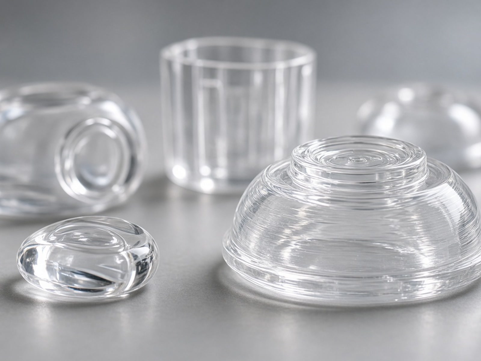
Clear resin 3D printing utilizes high-precision stereolithography to manufacture parts with exceptional feature detail and optical clarity. RapidPrintParts operates eight SLA machines dedicated to engineering resins, serving functional prototyping, fit checks, and assembly validation.
Typical Applications & Industrial Use Cases
Clear resin components are engineered for applications where internal feature visibility, fluid mechanics, or assembly mating must be directly observed before commitment to tooling.
Functional Fit Prototypes
Verify spatial alignment, internal clearances, and multi-part interfaces within complex mechanical enclosures before volume production.
Appearance Models
High-detail physical models for engineering design reviews, customer presentations, and ergonomic assessments requiring clean optical presentation.
Flow & Sensor Housings
Low-volume transparent components enabling non-destructive observation of internal fluid flow, valve behavior, and sensor alignments.
Target Industries: RapidPrintParts provides these components specifically for machinery, automation, robotics, and industrial hardware sectors where functional clarity aligns with demanding operating conditions.
Material Selection & Evaluation Factors
Clear resin provides high detail resolution, making it preferable when visibility and precision take precedence over the high rigidity or thermal limits of specialized opaque resins. Each design undergoes technical evaluation against several key operational factors:
-
Load, Temperature & Chemical Exposure Evaluation of physical stresses during operation. Load-bearing and elevated-temperature uses require direct engineering review.
-
Critical Dimensions & Finish Specifications Analysis of tight-tolerance interfaces and whether surface clarity can be achieved via standard SLA finishing or advanced secondary polishing.
-
Program Scope & Quantities Optimization for single-unit functional testing or ongoing batch runs across our dedicated machine park.
-
Post-Processing Requirements Determining the required optical level—ranging from natural semi-translucent build finish to optical clear polishing or tint dyeing.
Production Parameters & Envelopes
Allows single-piece production of large clear shells or consolidated multiple-component builds.
Baseline reference for standard geometry; final tolerances are verified per CAD model and build orientation.
Dedicated capacity ensures batch consistency and rapid turnarounds for iterative engineering projects.
Design Inputs & Secondary Finishing
Stereolithography parts require specific design allowances to maximize optical results and dimensional stability.
Support Structures
Support points attach to overhangs and may alter local surface texture, requiring careful orientation and manual removal.
Wall Thickness & Geometry
Uniform wall thickness minimizes internal refraction gradients and optical distortion while providing structural integrity.
Post-Processing Progression
Standard cleaning, manual wet sanding, machine polishing, or vapor smoothing can substantially elevate clarity, configured to application requirements.
Quality Control & Technical Documentation
Industrial integration demands traceability and measurable compliance. Quality assurance commitments are established individually based on project specifications.
Request Technical Evaluation
Submit your CAD files for technical assessment by the RapidPrintParts engineering team. We review part orientation, transparency targets, tolerances, and production schedule.
Required Submission Details
- 3D CAD Model (STEP, STP, or IGES format)
- 2D Technical Drawing with critical tolerances (if applicable)
- Surface finish requirement (raw, sanded, or optical clear)
- Operating context (temperature, assembly load, fluid contact)
Contact RapidPrintParts
Get in Touch
We are here to answer your questions about industrial additive manufacturing and functional 3D printed parts. Reach out to us through the following methods:
Email: [email protected]
Address: No. 17-1, Guanlan Avenue, Longhua District, Shenzhen, Guangdong Province, Shenzhen 3D Printing Industrial Park