Integrating 3D Printing and CNC Machining for Industrial Parts
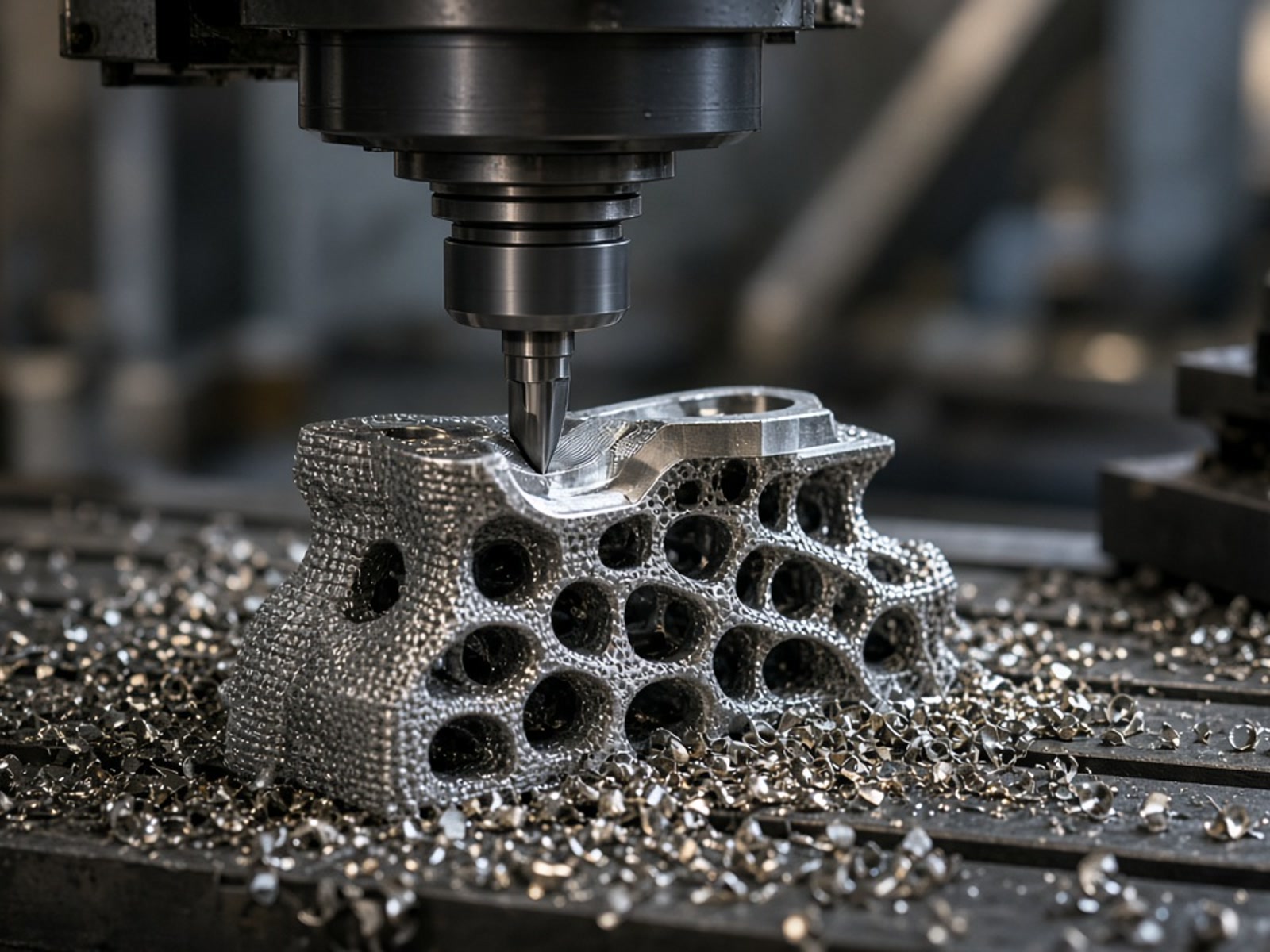
In industrial manufacturing, the choice between additive manufacturing and subtractive CNC machining is rarely binary. At RapidPrintParts, we utilize CNC secondary machining as a high-precision finishing operation to elevate the functional accuracy of industrial 3D-printed components.
Functional Enhancement
Why Combine 3D Printing with CNC Machining?
While additive manufacturing processes such as FDM, SLA, SLS, and MJF excel at building complex geometries, internal channels, and consolidated assemblies, mechanical interfaces often demand tighter tolerances. Secondary CNC machining bridges this threshold.
Precision Interfaces
Secondary milling creates perfectly flat, parallel, or perpendicular mating contact planes required for rigid multi-part assemblies.
Threaded Features
Direct CNC tapping and drilling deliver clean, accurate pitch and hole concentricity for critical hardware fastening where printed threads prove insufficient.
Dimensional Correction
Precision reaming and boring drive critical bearing pockets, dowel locations, and sleeve fits into true mechanical alignment.
Surface Refinement
Targeted post-machining completely strips support interfaces and refines localized functional faces to superior seal and glide finishes.
Technical Feasibility
Engineering Considerations for Secondary Machining
Not all 3D-printed parts are suited for subtractive processing. Proper mechanical execution requires assessing cutting force resistance, thermal stability, and datum repeatability prior to spindle engagement.
Engineering Advisory:
Guaranteed tolerances require pre-production engineering evaluation of CAD geometry, fixturing surfaces, and composite reinforcement orientation.
Polymer & Composite Material Selection
Substrates must withstand rotational cutter friction without melting, softening, or delaminating. Reinforced engineering filaments such as carbon-fiber filled polymers (PA-CF) or high-performance PEEK demand specialized toolpath velocities, sharp geometries, and heat mitigation.
Wall Thickness & Geometric Structural Rigidity
Workpieces must possess sufficient volumetric mass to counter clamping pressure and lateral tool loading. Thin-walled features or low-infill volumes risk deflection, micro-cracking, or dimensional chatter under cutter pressure.
Datum References & Clamping Envelopes
Subtractive setups require unambiguous datum references. Clear, non-deformed locating planes in your CAD model ensure our machinists can accurately touch off, establish coordinate zero, and hold alignment relative to internal additive geometry.
Integrated Execution
The Hybrid Production Flow
From CAD review to final verification, our end-to-end routing ensures functional precision on high-performance additive polymers.
Additive Build
The base component is produced via in-house polymer technologies—FDM, SLA, SLS, or MJF—with stock allowance applied to target features.
Engineering Review
Application engineers assess 3D CAD files alongside 2D geometric dimensioning to establish fixturing feasibility and tolerance validation.
Secondary CNC Machining
The printed part is rigidly fixtured for multi-axis subtractive milling, precise hole drilling, tapping, or surface fly-cutting operations.
Quality Inspection
Post-machined features undergo dimensional and surface verification against print specifications before mechanical release.
Project Scoping
Parameters for Secondary Machining Assessment
We tailor the workflow strictly to your operating environment. When preparing an RFQ involving hybrid processing, prepare the following inputs:
Application & Working Environment
Specify operating temperatures, structural cyclic loads, chemical contact, and mating assembly configurations to determine appropriate base polymers (e.g., PA12, PEEK, or carbon-reinforced composites).
Feature-Specific Tolerances
Identify exactly which faces, holes, or bearing counterbores require subtractive tolerances. Keep non-critical cosmetic contours additive to preserve budget efficiency.
Production Volume & Intent
Indicate whether the project represents a functional prototype, short-run validation batch, or bridge-to-tooling production run to optimize custom fixturing strategies.
CAD Model & 2D Engineering Drawings
Submit standard 3D files (STEP/STP) coupled with a 2D PDF drawing calling out designated datum references, thread specifications, and explicit tolerance envelopes.
Request an Engineering Review
Every industrial application presents distinct structural and functional requirements. Our team evaluates your additive design against secondary CNC milling, drilling, and tapping processes to verify manufacturing feasibility before production begins.
Supported Additive Platforms
Contact RapidPrintParts
Get in Touch
We are here to answer your questions about industrial additive manufacturing and functional 3D printed parts. Reach out to us through the following methods:
Email: [email protected]
Address: No. 17-1, Guanlan Avenue, Longhua District, Shenzhen, Guangdong Province, Shenzhen 3D Printing Industrial Park